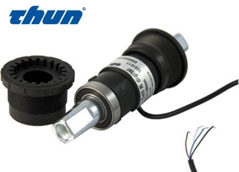
Thun Sensor X-Cell RT Digital 128k/123mm Original Thunsensor för elcyklar. Tack vare Thuns teknik att montera PCME sensorn i det inre lagret så är sensorn väl skyddad från vibrationer, olja och smuts. Detta gör att underhållet är minimalt. Thuns sensorer är designade för att klara tuffa tag och ge dig en följsam cykling. Technical Data TYPE/ DESIGNATION: 128 K REFERENCE SIZE [mm]: 123 DIMENSIONS RIGHT-HAND-SIDE L2* ±0.5 mm [mm]: 28.40 DIMENSIONS LEFT-HAND-SIDE L3* [mm]: 26.60 TOTAL LENGHT OF SPINDLE Lges ±1.0 mm [mm]: 128.00 Description of assembly Prior to assembly, the bottom bracket’s bore and tubes must be checked and any burrs that might interfere with ,the cable must be removed (according to EN 15194:2009). This is to prevent damage to the cable. Further, it is crucial that the inner diameter of the bottom bracket is not cylindric however large enough in order to guarantee enough space for the cable. • Screw the left-hand adapter (with RIGHT-HAND thread, Fig. 3) into the left side of the bottom bracket (Fig. 4) and tighten it to a torque of 25 - 30 Nm. • Be advised to choose the right diameter of the drill-hole for the cable or plug feedthrough for the to be mounted X-CELL. • Hold the BB-cartridge (Fig. 5) in front of the opening on the right-hand side of the bottom bracket (Fig. 6). Introduce the cable through the bottom bracket and through the drill hole, into the required frame tube, and push until it exits the end of the tube. Then either hold the end of the cable or secure it with a cable tie. • Insert the BB-cartridge (Fig. 6) carefully into the bottom bracket so that the cable is on the same direction as the chosen frame tube. As you do so, pull gently on the cable so that it does not snag as the cartridge is inserted into the frame. • While inserting the BB-cartridge into the bottom bracket, make sure that there is no excessive resistance. • If there is excessive resistance, it may be that the projections on the sensor shell (Fig. 7) are not correctly aligned with the grooves in the left-hand adapter (Fig. 8). Another reason might be that there is not enough space for the cable within the bottom bracket. • Hold the end of the cable and screw in the right-hand adapter (the cable should not be pulled!). Then tighten the right-hand adapter to a torque of 25-30 Nm. • Please pay attention to the following connection diagram during the assembly of the X-CELL (Fig. 9): Wirecolor Description Black - Ground White - power supply Grey - Torque signal Brown - Sinus signal Blue - Cosinus Signal The sinus and cosinus signal is used to detect the rotation direction and cadence of the X-CELL spindle and must be adapted to the programming of the controller. Important to know is if you are changing from a K-version to a L-version the signal of the rotation direction is also inverted. Innehåll: 1 st sensor OBS. Produktbilder kan skiljas sig något mot levererad produkt, se tekniska specifikationen. Produkten är i första hand avsedd för proffessionella användare och kräver tekniskt kunnande för att installeras. Skickas från vårt lager i SVERIGE.
